Contents
- 1 1. Introduction
- 2 2. Applicable Standards and Clauses
- 3 3. Objectives of Earthing
- 4 4. Earthing System Components
- 5 5. Types of Earthing Systems (IEC 60364-1)
- 6 6. Design Criteria and Calculations (per IEEE 80 and IEC 60364-5-54)
- 7 7. Difference Between Types of Earthing
- 8 8. Saudi Standards Requirements (SBC, SEC)
- 9 9. Testing and Maintenance
- 10 10. Typical Applications and Recommendations
- 11 11. Sample SLD of Earthing System
- 12 12. Conclusion
(As per IEC, IEEE, SBC, and NEC standards)
1. Introduction
Earthing (also called grounding) is a vital aspect of any electrical installation. It provides a low impedance path for fault current, ensuring safety for personnel and protection of equipment. A properly designed earthing system is essential for both functional performance and compliance with international standards.
2. Applicable Standards and Clauses
| Standard | Reference Clause | Key Requirement |
|---|---|---|
| IEC 60364-5-54 | Clause 542, 543 | Design rules for earthing arrangements and protective conductors |
| IEC 60947-2 | Annex A | Earthing requirement for protective devices |
| IEEE 80 | Sections 7–14 | Grounding design for substations |
| BS 7430 | Full standard | Earthing system design, testing, and installation practices |
| Saudi Building Code (SBC 401 – Electrical) | Clause 401.10.1 to 401.10.9 | National earthing and bonding requirements |
| NEC (NFPA 70) | Article 250 | Grounding and bonding requirements in buildings |
3. Objectives of Earthing
- Safety of human life from electric shock
- Protection of equipment and appliances
- Providing a reference potential for the system
- Ensuring fast clearance of faults by enabling effective operation of protective devices
- Lightning and surge protection
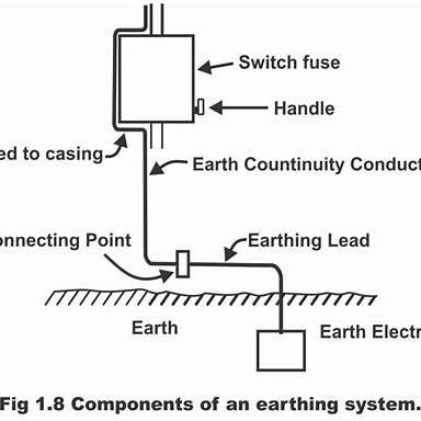
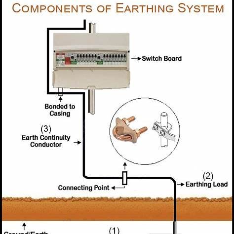
4. Earthing System Components
| Component | Function |
|---|---|
| Earth Electrode (Rod/Plate/Mat) | Provides physical connection to earth |
| Earthing Conductor | Connects equipment to earth electrode |
| Main Earthing Terminal/Bar | Common point of all earth conductors |
| Earth Busbar | Distribution bar for multiple earth connections |
| Soil Enhancing Material | Reduces soil resistivity (e.g., bentonite, conductive concrete) |
| Test Links | Allows disconnection for testing earth resistance |
| Bonding Conductors | Equalize potential difference across metallic parts |
5. Types of Earthing Systems (IEC 60364-1)
| System Type | Definition | Application |
|---|---|---|
| TN System | Source neutral connected to earth; protective earth (PE) and neutral (N) conductors are separate or combined | Industrial, residential |
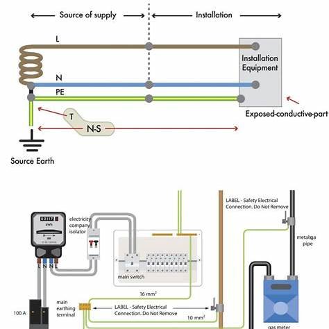
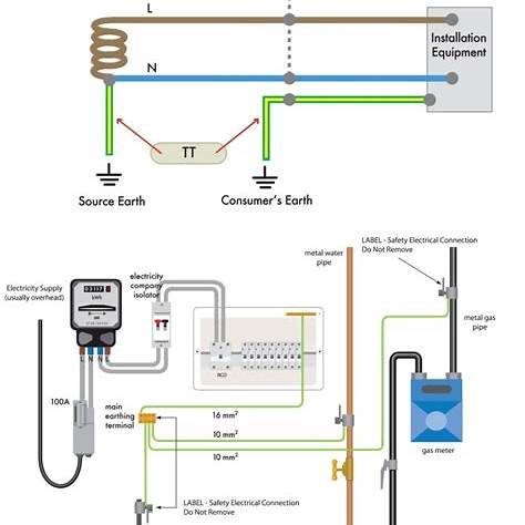
| TT System | Neutral earthed at source; exposed conductive parts connected to a local earth electrode | Rural areas |
| IT System | Neutral isolated or connected via impedance; exposed parts earthed | Hospitals, sensitive environments |
TN System Subtypes:
- TN-S: Separate PE and N from the source
- TN-C: Combined PEN (protective earth and neutral)
- TN-C-S: Combined up to a point, then separate
6. Design Criteria and Calculations (per IEEE 80 and IEC 60364-5-54)
6.1 Earth Electrode Resistance
- General Target: ≤ 1 Ω (critical systems), ≤ 5 Ω (standard installations)
- Calculation (for rod electrode): R=ρ2πL⋅(ln(4Ld)−1)R = \frac{ρ}{2πL} \cdot \left( \ln\left(\frac{4L}{d}\right) – 1 \right)R=2πLρ⋅(ln(d4L)−1) Where:
- RRR = Resistance in ohms
- ρρρ = Soil resistivity (Ω·m)
- LLL = Length of rod (m)
- ddd = Diameter of rod (m)
6.2 Touch and Step Voltage
- IEEE 80 provides equations: Vstep=ρ⋅If2πDV_{step} = \frac{ρ \cdot I_f}{2πD}Vstep=2πDρ⋅If Vtouch=ρ⋅If2πSV_{touch} = \frac{ρ \cdot I_f}{2πS}Vtouch=2πSρ⋅If
- IfI_fIf: Fault current
- DDD, SSS: Distance from electrode
6.3 Equipotential Bonding
- All metallic enclosures and building structural steel must be bonded to the main earth bar.
7. Difference Between Types of Earthing
| Aspect | TN-S | TN-C | TT | IT |
|---|---|---|---|---|
| PE/N Separation | Separate | Combined | Separate | Separate |
| Fault Clearance | Fast | Fast | Depends on RCD | Slow/Alert-based |
| Earth Fault Current Path | Low impedance | Low impedance | Through soil | Limited current |
| Application | General | Cost-efficient | Remote/rural | Critical systems |
| Protection Device | MCB/ELCB | MCB | RCD | Isolators/alarms |
8. Saudi Standards Requirements (SBC, SEC)
- Main Earth Electrode Resistance: ≤ 1 Ω (substations), ≤ 5 Ω (buildings)
- Use of Copper Tape/Bar: Minimum 25×3 mm copper bar for equipment earthing
- Testing: Pre-commissioning earth resistance test per SBC Clause 401.10.6
- Connection Method: Exothermic welding preferred (Kingsmill or Cadweld)
9. Testing and Maintenance
Testing Methods:
- Fall-of-potential (3-point method)
- Clamp-on method (for loop resistance)
- Soil Resistivity Test: 4-point Wenner Method (for new sites)
Maintenance Frequency:
- Visual inspection every 6 months
- Earth resistance test annually
10. Typical Applications and Recommendations
| Installation | Recommended Earthing |
|---|---|
| Data Center | TN-S with separate clean earth |
| Residential | TN-C-S or TT (if RCD used) |
| Hospital | IT System (for medical IT circuits) |
| Industrial Plant | TN-S with equipotential bonding |
| Substation | IEEE 80-compliant grid earthing |
11. Sample SLD of Earthing System
A diagram showing TN-S system with incoming supply, transformer neutral earthing, main earth bar, bonding to metallic parts, and earth electrode system.
(Will be included in the final PDF/PowerPoint version with technical drawing.)
12. Conclusion
The earthing system is the backbone of electrical safety and system stability. A properly engineered earthing design not only ensures compliance but also protects lives, assets, and continuity of operations. It must be tailored to the site soil condition, fault levels, application type, and relevant local/international codes.
1. User discussion area
2. Link to free standards pdf or upload them
3. Add index at start
4. Detail of earthing equipment including accessories
5. Installation details
6. Comparison of earthing systems with figures and how to choose
7. Testing procedure detail with figures